


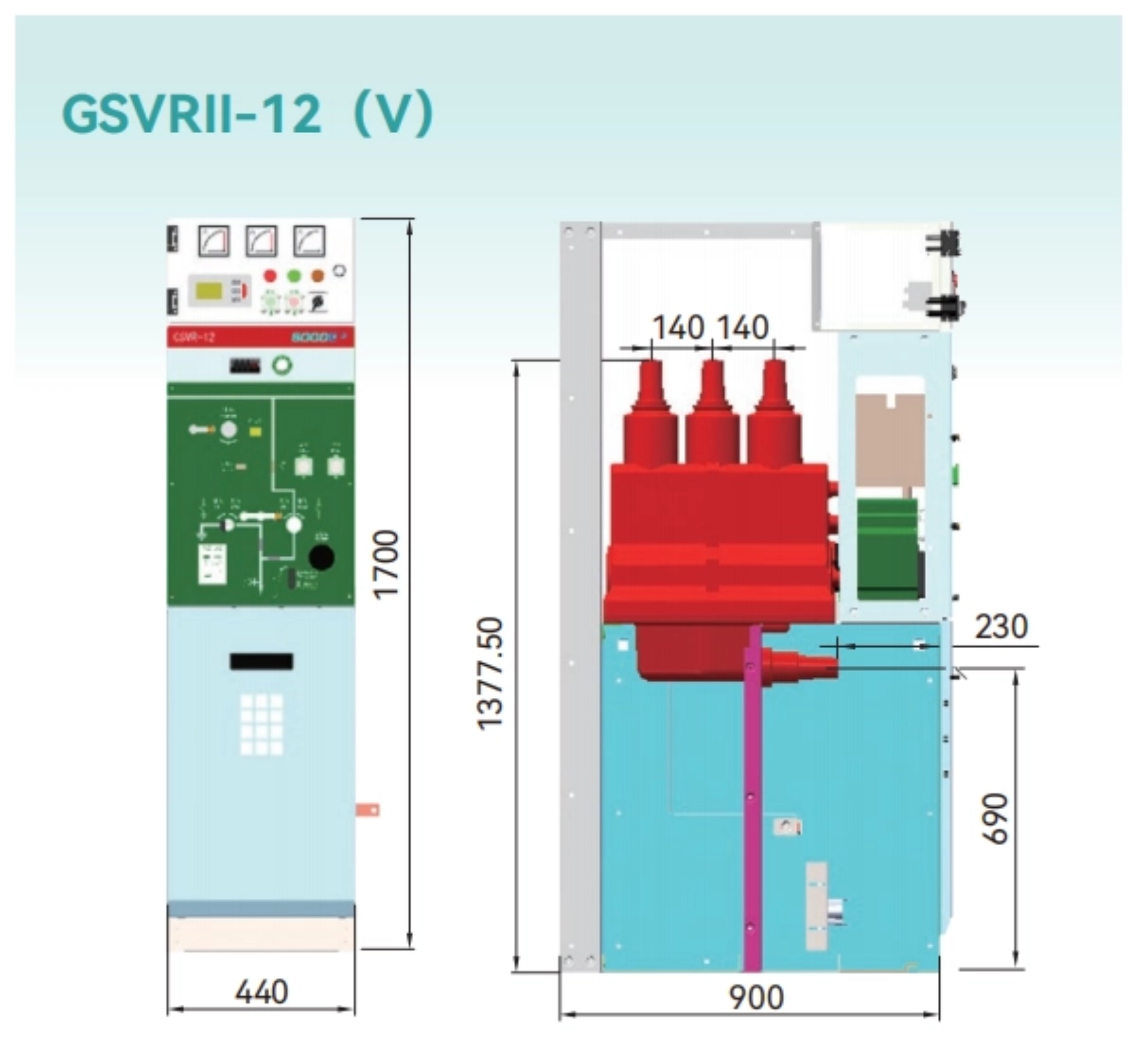
GSVR Ⅱ -12 (V)
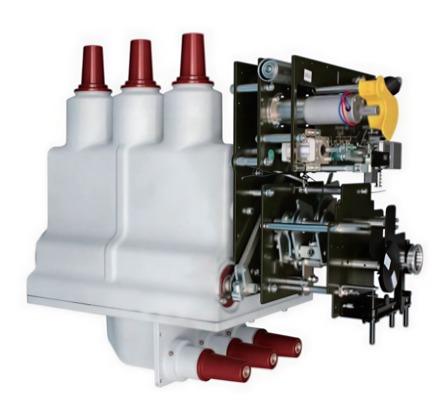
1.Vacuum interrupter and three-position disconnector are monolithically encapsulated within a single epoxy insulation housing, achieving maximized compactness with simplified construction for streamlined installation.
2.The fully cast monolithic sealing structure is engineered for 5,000-meter altitude operation, effectively preventing insulation performance degradation under low-pressure conditions
-
Detail
GSVR-12 Switch Features
1.Vacuum interrupter and three-position disconnector are monolithicallyencapsulated within a single epoxy insulation housing, achievingmaximized compactness with simplified construction for streamlinedinstallation.
2.The fully cast monolithic sealing structure is engineered for 5,000-meteraltitude operation, effectively preventing insulation performancedegradation under low-pressure conditionsOperating Conditions
GSVR-12Altitude≤5000m
TemperatureMaximum50℃Minimum-40℃Average within 24h≤35℃HumidityAverage relative humidity within 24h≤95%Monthly average relative humidity≤90%EnvironmentSurrounding air free of explosive, corrosive gases,installation site free of severe vibration and impact
Notes
Please contact us for requirements exceeding the above conditions.
GSVR-12 Series
The GSVR I/II series solid-insulated switches employ a downward isolation configuration, offering two functional unit options: circuit breaker (CB) and switch-fuse combination. For insulation treatment, two external surface variants are provided: zinc-sprayed and non-zinc-sprayed. The zinc-sprayed version utilizes a proprietary arc zinc fusion process that metallurgically bonds a uniform, dense zinc layer to the epoxy resin housing surface. This achieves a fully shielded and grounded design (achieving equipotential bonding), effectively equalizing electric field distribution, suppressing partial discharge (PD), and ensuring personnel safety during contact operations.
Primary Circuit
Circuit Breaker
1.Employs vacuum arc interruption technologyto ensure high breaking capacity and longelectrical life.
2.The shaft support within the transmissionsystem extensively uses precision needleroller bearing design, ensuring flexiblerotation and high transmission efficiency
Disconnector
1.Three-position design theoretically eliminatesmisoperations through intrinsic interlocking.
2.Creepage and clearance distance betweenthe isolation blade and groundingcontact/stator contact is 125mm, ensuringinsulation reliability
3.High-performance disc springs ensurestability of contact pressure.
4.Contact design favorable for closing shape,grounding closing speed ≥4.2m/s, ensuringgrounding closing reliability.
3.Optimized Division of Protection Duties:Fuses assume short-circuit and overloadprotection functions, while the load switchhandles rated current and transfer currentclosing operations. This significantly reducesthe load switch's breaking capacity requirements
Load Switch-Fuse Combination
1.Precision Coordinated Protection:Under transfer current conditions ≤3150A, the load switch and fuse achieve precisecoordination to eliminate protection blindspots, ensuring comprehensive fault coverageacross the entire operational range.
2.Phase-Loss Prevention Mechanism:During single-phase fuse operation, the tripping striker activates the mechanicalrelease mechanism to initiate three-phasesimultaneous opening of the load switch,completely eliminating risks associated withsingle-phasing operation.and extends its mechanical lifespan
4.High-Efficiency Maintenance Design:The fuse cartridge employs a modular quick-con nect/disconnect design, substantially reducingboth fuse replace ment time and poweroutage duration, thereby enhancing operationaland maintenance efficiency
Operating Mechanism
Circuit Breaker/Load Switch Operating Mechanism
1.Components like the main switch mechanism'smotor, auxiliary switch, release, and limit switchare readily replaceable, facilitating productmaintenance.
2.Dual-spring precision transmission designwith reclosing function.
3.Main switch mechanism features automaticcounting to meet grid requirements.
4.All transmission components are made of high-quality quenched and tempered steel and hardened steel,ensuring a long service life.
5.Core transmission uses needle roller bearingdesign, offering strong impact resistance,high load capacity, and low friction.Disconnector Mechanism
1.Isolation mechanism uses a three-positionsingle-spring design with two independentoperating shafts, theoretically eliminatingmisoperations.2.Isolation operating mechanism can beequipped with an electric option.
3.Dual-clutch technology allows freeswitching between manual and electricoperation.
4.Output shaft uses gear accelerationdesign, offering high output efficiency,large transmission power, and groundingclosing speed ≥4.2m/s.
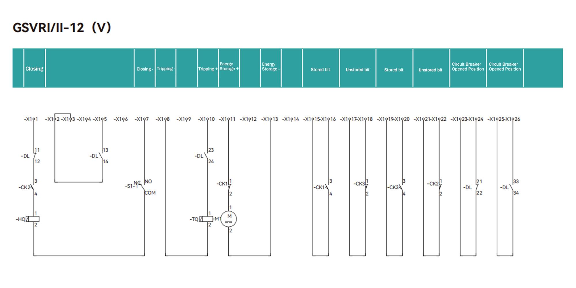
Electrical Schematic Diagrams
 Equipment NoEquipment NameQuantity-DLCircuit Breaker
1 HQCircuit Breaker Closing Coil1 TQCircuit Breaker Tripping Coil1 M1Circuit Breaker Spring Energy - storage Motor1 CK1Spring Energized Travel Switch1 CK2Spring Energized Travel Switch1 CK3Spring Energized Travel Switch1 S1-1DisconnectorTravel Switch1 S1-2Disconnector Travel Switch1 S1-3Disconnector Travel Switch1 S3-1Earthing Switch Travel Switch1 S3-2Earthing Switch Travel Switch1 S3-3Earthing Switch Travel Switch1 EL1Light1 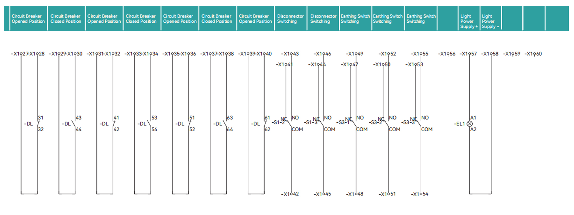
Typical Application Schemes
GSVR-12 Series Primary Main Wiring Scheme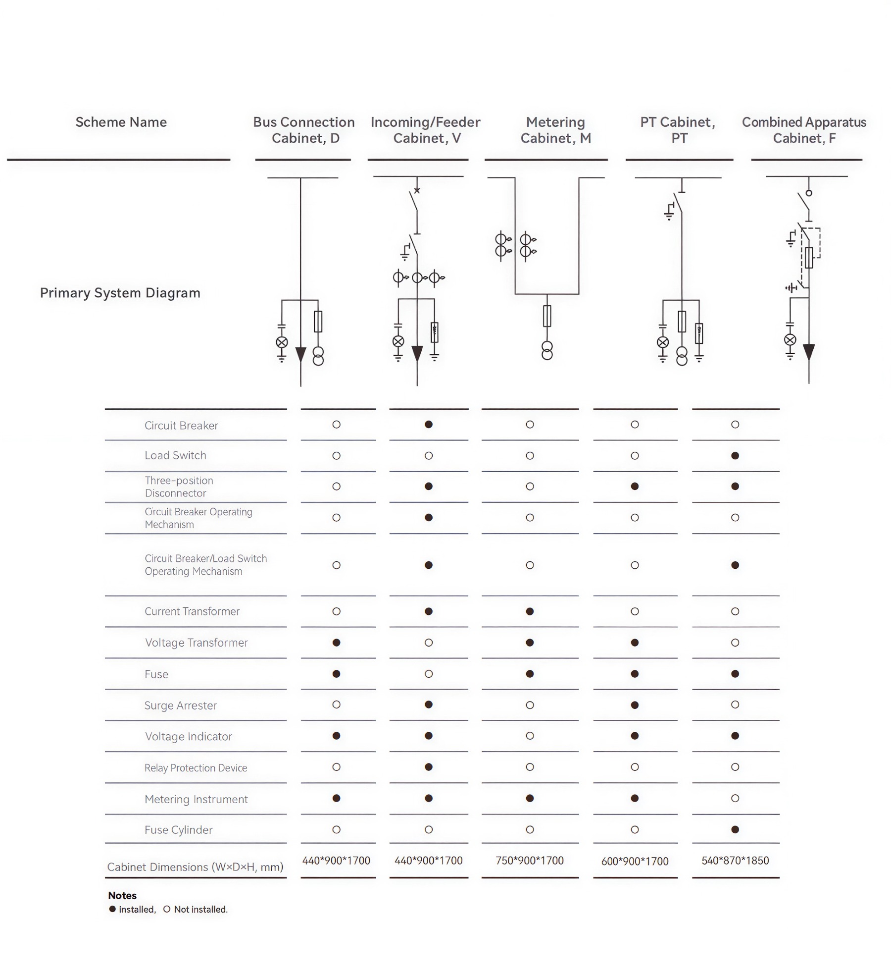
Typical Application Schemes
-
Customer ReviewsNo comments